Pneumatic averaging
A common positive- and negative-pressure circuit feeds one DP transmitter. The complete supplied array uses an approved system coefficient.
Patented multi-point velocity-array measurement
A patented multi-point differential-pressure array engineered for large circular pipes, rectangular ducts and gas-flow profiles that a single-point or single-bar probe may not represent.
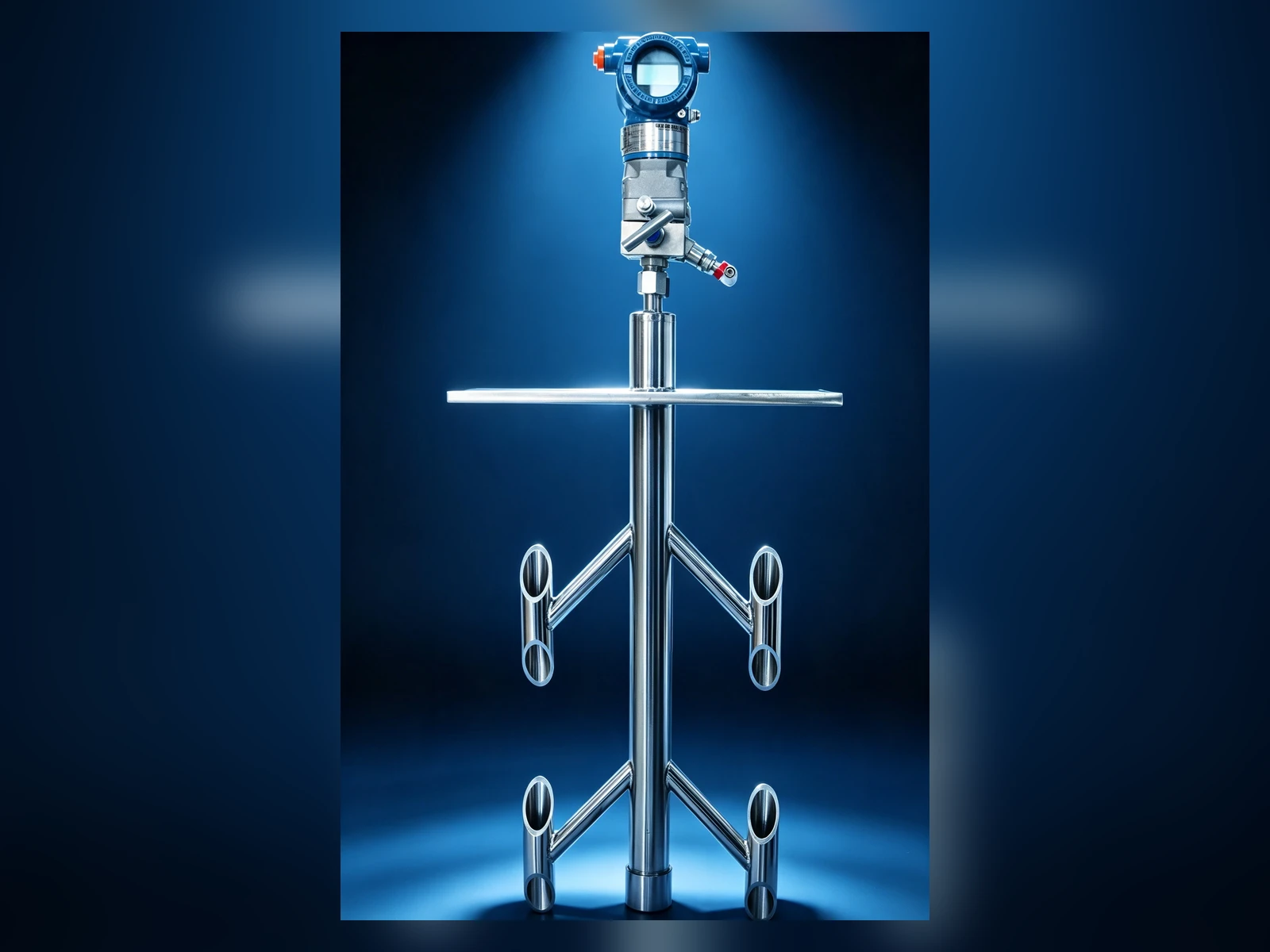
Shizhong Full-Section Matrix Flowmeter
Image 1 of 3 · Auto-advances every 3.2 seconds
ONE ARRAY · THREE SIGNAL ARCHITECTURES
A matrix array samples more of the section than a single probe, but pressure averaging is not automatically the same as arithmetic velocity averaging. Shizhong selects the signal architecture, grid, coefficient and acceptance method together so that the delivered calculation matches the actual duct and measurement objective.
A common positive- and negative-pressure circuit feeds one DP transmitter. The complete supplied array uses an approved system coefficient.
Separate duct zones provide diagnostic visibility when the profile is asymmetric or the operating load changes substantially.
Local velocities are calculated from individual DP channels and integrated with defined area weights for the strongest traceability.
Patented Shizhong architecture
CN212082473U covers the combination of an upstream flow conditioner, symmetric multi-branch positive-pressure array, downstream negative-pressure structure and centralized pressure connections. The patent establishes the structure; project performance remains tied to the supplied geometry and approved verification basis.
Standards boundary
ISO 3966:2025 informs Pitot-static velocity-area practice. ISO 16911-1/-2 supports stationary-source reference and automated measurement. Neither standard assigns a universal coefficient, accuracy or straight run to a proprietary matrix array, and ISO 5167 does not cover this product class.
The Shizhong Full-Section Matrix Flowmeter combines a multi-point sensing array with an integrated flow-conditioning structure to sample a broader area of the measuring section. Each system is designed around the actual duct geometry, upstream disturbance, gas properties, maintenance conditions and acceptance method. Project performance is established through an approved system coefficient, representative calibration or site correlation—not a universal coefficient transferred between installations.
Final specifications are confirmed against process data, piping, material, pressure class, applicable code and metrology requirements.
ENGINEERING ANSWER UNITS
These product-specific answers retain the source evidence, calibration limits and conditions where a different measurement route is preferable. Values that cannot be confirmed from the approved source remain subject to project review or pending field test; no unverified value is supplied here.
Dataset v1.5.0; last reviewed 2026-08-24. Evidence IDs are retained in the translation dataset.
Replacement: In a large-section duct, a matrix flowmeter can replace a single-point or single-bar probe that does not represent the section adequately. A grid of multi-point total-pressure and matched negative-pressure circuits provides zoned velocity information. Use it when: The duty is flue-gas CEMS, a large low-velocity duct, or boiler forced- or induced-draft air and the array, zones and supports must be designed from the sectional velocity distribution. Do not force the substitution when: Do not apply this flue-gas and duct CEMS matrix route to pipe liquids, steam DP measurement or small pipes.
COMPARISON REPLACEMENT · MEDIUM source confidence
Recommended application: Use a matrix route for flue-gas CEMS, large low-velocity ducts and boiler forced- or induced-draft air when a single-point or single-bar probe is not representative and a multi-point array can be designed from the velocity distribution and calibrated or site-compared. Prefer another route when: Do not apply a duct CEMS matrix route to pipe liquids, steam DP measurement or small pipes; compare a standardized primary element or another applicable product. Standards basis: HJ 75, HJ 76, GB/T 16157 and DL/T 2618, with ISO 3966:2025 and ISO 16911-1/-2 as references. GB/T 2624 does not apply; the approved calibration or site-comparison basis governs.
RECOMMENDATION COMPARISON · HIGH source confidence
Confirm by application. The historical product-family range of -100~850℃ requires material and mechanical review. Confirm pressure by application; pressure boundary, supports, connections and design code require review. The historical temperature sample is not an unconditional finished-product commitment.
TEMPERATURE PRESSURE · MEDIUM source confidence
Circular sections: 25—6000 mm. Rectangular sections: 50 × 50~4000 × 4000 mm, as the product-family engineering range. Final array count, zoning and support design are project-specific to the duct section and velocity distribution.
DIAMETER RANGE · HIGH source confidence
304 or 316L stainless steel is available. Duplex stainless-steel and nickel-alloy options require corrosion and mechanical review. Material selection must also account for flue-gas corrosion, erosion, temperature and the support structure.
MATERIALS LINING · MEDIUM source confidence
Accuracy is ±0.5% after individual flow calibration and is stated only as covered by the certificate. Historical ±0.5%, ±1.0% and ±1.5% classes require an approved calibration or site-comparison basis. Standards basis: CN212082473U; HJ 75 / HJ 76; GB/T 16157; DL/T 2618; ISO 3966:2025 / ISO 16911-1/-2 as references. GB/T 2624 does not apply. Flue-gas and duct CEMS applications follow the HJ 75 / HJ 76 site-comparison requirements.
CALIBRATION ACCURACY · MEDIUM source confidence
Symptom: Zoned readings disagree, the total fluctuates, or some points have no signal. Possible causes: Blocked probe pressure openings, blocked or leaking zoned impulse lines, displaced array supports or orientation, a changed velocity distribution, or an acquisition-channel or transmitter fault. Action: Check power, wiring and zero channel by channel, then leak-test and purge each zone and verify array position. Perform a site comparison to HJ 75, HJ 76 and the project plan if required.
TROUBLESHOOTING · MEDIUM source confidence
Request a detailed datasheet with dimensional drawings, material certificates and ordering information for Full-Section Matrix Flowmeters.
Production and documentation schedules are confirmed in the quotation after technical review and drawing approval.
Send your process data for an engineering review and a project-specific next step.