Multi-hole flow conditioning
Balanced Flow Meters — Conditioning DP Flow Meter
Pipeline, wafer and replaceable-core differential-pressure meters with an application-specific multi-hole primary element for compact industrial flow measurement.
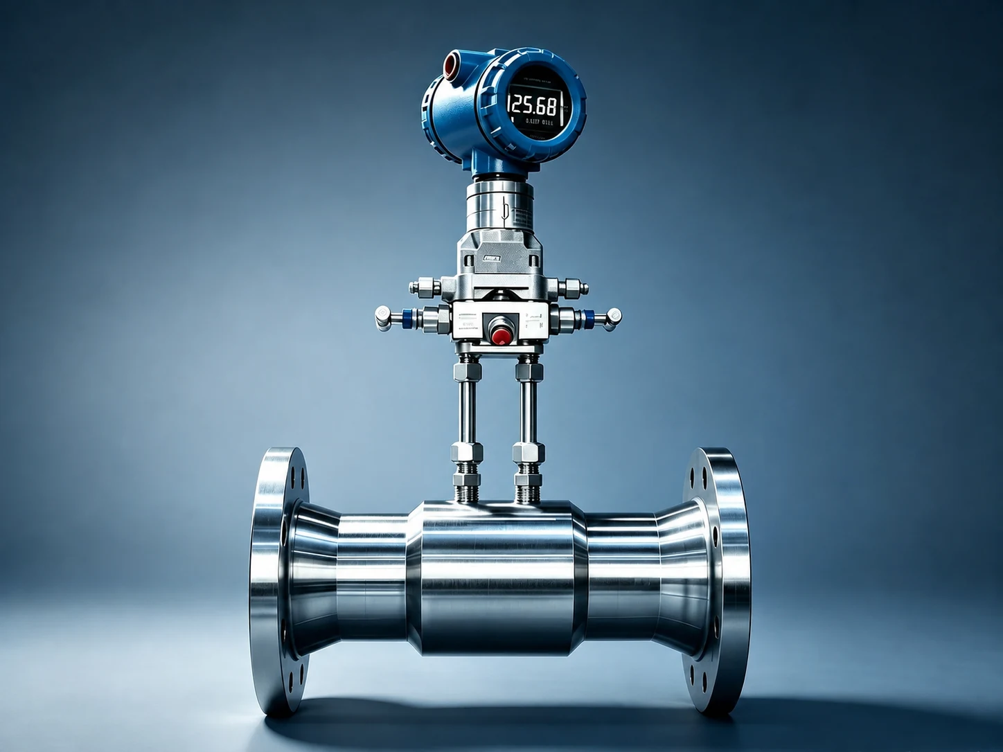
Pipeline-Type Balanced Flow Meter
Image 1 of 3 · Auto-advances every 3 seconds
Wide-range measurement built around your process
Balanced flow meters use a project-specific multi-hole primary element to generate differential pressure while redistributing the velocity profile. Routine supply covers DN50–DN600; low-pressure large-diameter service is available from DN650 to DN2000, with Series A or B selected to match the pipe outside diameter. Every supplied meter requires individual flow calibration.
Key design features
Related Solutions
Typical applications
Natural-gas pressure-regulating skids
Industrial gas and compressed-air systems
Water and process-liquid measurement
Steam and energy metering
Final specifications are confirmed against process data, piping, material, pressure class, applicable code and metrology requirements.
ENGINEERING ANSWER UNITS
Application boundaries, selection and troubleshooting
These product-specific answers retain the source evidence, calibration limits and conditions where a different measurement route is preferable. Values that cannot be confirmed from the approved source remain subject to project review or pending field test; no unverified value is supplied here.
Dataset v1.5.0; last reviewed 2026-08-24. Evidence IDs are retained in the translation dataset.
How does a balanced flow meter differ from other meters, and when can it replace them?
Replacement: Where wider turndown or shorter straight runs are required, a balanced flow meter can replace an orifice plate and can correspond to an imported Keyon A+K balanced-meter route. Use it when: Straight pipe is severely limited, bidirectional flow or wider turndown is required, and the installation boundary can be established for the specific geometry and calibration conditions. Do not force the substitution when: Very dirty or fibrous fluid may block the small bores; or the project insists on ISO standardized geometry without flow calibration and cannot verify β and the calibration basis. Keyon and A+K are trademarks of their respective owners; this comparison uses public information available as of 2026-08, is not affiliated with the owners, and is not intended to disparage them.
COMPARISON REPLACEMENT · HIGH source confidence
When is a balanced flow meter recommended, and when should another measurement route be compared?
Recommended application: Use a balanced flow meter where straight pipe is severely limited, bidirectional measurement is required, or a wider turndown is needed, provided the installation boundary is established from the actual multi-hole geometry, adjacent fittings and calibration conditions. Typical duties include injection and withdrawal at salt-cavern or depleted-reservoir gas storage, interconnected multi-source district-heating networks, and intercompany steam networks. Prefer another route when: The fluid is very dirty or fibrous and small passages may block, or the project insists on ISO standardized geometry without flow calibration. Compare a wedge meter, standard orifice plate or another applicable route. Standards boundary: The balanced meter is engineered by reference to ISO 5167-1:2022 principles; the Shizhong supply route requires individual flow calibration, and final performance follows the corresponding certificate.
RECOMMENDATION COMPARISON · HIGH source confidence
What temperature and pressure can a balanced flow meter handle?
Body-material design-temperature range: -196~600℃. The fluid-temperature limit and temperature-pressure combination require a second project review of materials, pressure class, seals, instrumentation and mechanical design. Pressure: PN2.5—PN420 / ASME Class 150—2500, subject to project-specific design confirmation.
TEMPERATURE PRESSURE · MEDIUM source confidence
What sizes are available for a balanced flow meter?
Standard range: DN50—DN600. Low-pressure large-bore designs from DN650—DN2000 are available, with DN650 and above adapted to the applicable A/B pipe outside-diameter series. Large-size feasibility still depends on pressure and project design.
DIAMETER RANGE · MEDIUM source confidence
Which materials are available for a balanced flow meter?
304 stainless steel, 316L stainless steel, carbon steel and Hastelloy C-276 are available. Final selection must account for corrosion, the temperature-pressure combination and the manufactured construction.
MATERIALS LINING · MEDIUM source confidence
How is a balanced flow meter calibrated, and how is accuracy confirmed?
Accuracy is ±0.5% after individual flow calibration and is stated only as covered by the certificate. The Shizhong balanced-meter supply route requires flow calibration; final accuracy is confirmed only by the corresponding project datasheet and calibration certificate.
CALIBRATION ACCURACY · MEDIUM source confidence
How should straight runs and orientation be confirmed when installing a balanced flow meter?
As an engineering rule, straight runs are approximately 1/2~1/3 of those for an orifice plate in the same duty and remain project-specific. “0.5D upstream and 0.5D downstream” is only a reference for particular geometries and calibration conditions, not a universal installation value. Before installation, also verify multi-hole plate orientation, concentricity, gasket position and pressure taps; the approved installation drawing governs.
INSTALLATION GUIDE · MEDIUM source confidence
What should be checked when a balanced flow meter is biased, fluctuates or produces no signal?
Symptom: The reading is biased, unstable or absent. Possible causes: Incorrect multi-hole plate orientation, blocked or leaking pressure taps or impulse lines, deposits in the bores, installation conditions outside the approved arrangement, or a manifold or transmitter fault. Action: Check the power supply, manifold and impulse system first. After isolation and depressurization, verify plate orientation and clean the passages, then check zero and range against the approved installation and calibration basis.
TROUBLESHOOTING · MEDIUM source confidence
Related products
Need full specifications?
Request a detailed datasheet with dimensional drawings, material certificates and ordering information for Balanced Flow Meters.
Production and documentation schedules are confirmed in the quotation after technical review and drawing approval.
Ready to discuss your application?
Send your process data for an engineering review and a project-specific next step.