Steam and energy outputs
Add synchronized pressure and temperature inputs when compensated mass flow, standard volume or energy is required. Dryness, condensate and wet-steam risk remain separate application checks.
Kármán-vortex measurement for steam, gas and clean liquids
Shizhong-manufactured full-bore vortex-shedding flowmeters for steady, single-phase steam, gas and clean-liquid service, with volumetric output and optional pressure/temperature compensation.
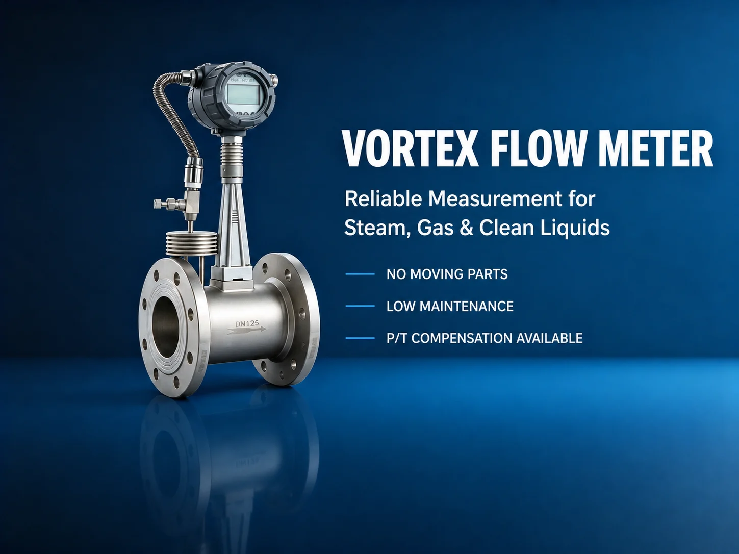
Vortex Flow Meter for Steam, Gas and Clean Liquids
Image 1 of 2 · Auto-advances every 3.2 seconds
VORTEX MEASUREMENT WITH A DEFINED APPLICATION BOUNDARY
A vortex meter converts shedding frequency behind a bluff body into flow. The principle offers no moving parts and a direct frequency output, but dependable performance still depends on single-phase flow, adequate Reynolds number, stable velocity, controlled piping disturbance and a vibration-aware installation.
Add synchronized pressure and temperature inputs when compensated mass flow, standard volume or energy is required. Dryness, condensate and wet-steam risk remain separate application checks.
The lower cut-off is set by Reynolds number, density, sensor signal and vibration—not by transmitter rangeability alone. Shizhong sizes the meter against minimum, normal and maximum conditions.
Elbows, valves, reducers, pulsation, pipe stress and mechanical vibration are reviewed before the straight-run and support arrangement are approved.
Applicable full-bore standards
These documents address vortex measurement in a full circular conduit for steady or slowly varying, single-phase liquid, gas or steam service. Their installation and influence-quantity guidance is applied together with the selected meter's approved datasheet and calibration basis.
Important boundary
ISO 12764 and ASME MFC-6 exclude insertion-type vortex meters. Any larger insertion design therefore needs its own geometry, coefficient, installation, structural and acceptance basis. ISO 5167 is a differential-pressure constriction standard and is not used as a vortex-product conformity claim.
A bluff body creates alternating Kármán vortices whose shedding frequency is proportional to mean velocity over the validated operating range. Shizhong manufactures and configures the primary sensor, electronics, process connection and optional pressure/temperature compensation for the actual medium and duty. Public performance is stated by model, size, fluid, Reynolds number and installation basis.
Final specifications are confirmed against process data, piping, material, pressure class, applicable code and metrology requirements.
ENGINEERING ANSWER UNITS
These product-specific answers retain the source evidence, calibration limits and conditions where a different measurement route is preferable. Values that cannot be confirmed from the approved source remain subject to project review or pending field test; no unverified value is supplied here.
Dataset v1.5.0; last reviewed 2026-08-24. Evidence IDs are retained in the translation dataset.
Replacement: A vortex flowmeter can correspond to an imported vortex meter such as Yokogawa or Endress+Hauser and can replace an orifice route in simple, stable clean-gas or steam service. Use it when: The fluid is clean, velocity is within the selected model's usable range, and the site values no moving parts, a frequency signal, and temperature-pressure compensation. Do not force the substitution when: Temperature exceeds the selected model's limit, vibration is continuously severe, or dirt and contaminants may foul the bluff body and cause signal loss; select a more suitable DP or other route. Yokogawa and Endress+Hauser are trademarks of their respective owners; this comparison uses public information available as of 2026-08, is not affiliated with those owners, and is not intended to disparage them.
COMPARISON REPLACEMENT · MEDIUM source confidence
Recommended application: Use a vortex meter for clean gas, steam or low-viscosity liquid when velocity is within the selected model's range, pipe vibration is controlled, and reducing impulse piping and routine maintenance points is valuable. Prefer another route when: The fluid is dirty or deposits readily, vibration is continuously severe, flow pulsates, velocity is too low, or temperature exceeds the selected model's approved range. Compare a DP or another applicable route. Standards basis: GB/T 25922-2023 and ISO 12764:2017; final installation follows the selected model and approved installation drawing.
RECOMMENDATION COMPARISON · HIGH source confidence
Temperature: -40~260℃ for the standard series; up to 400℃ for the applicable high-temperature model with remote electronics. Pressure: typically PN16 / PN25 / PN40. Final temperature and pressure ratings follow the approved datasheet and flange standard.
TEMPERATURE PRESSURE · HIGH source confidence
DN25—DN300 for the standard full-bore series. Larger insertion constructions require separate project review and must not be presented as part of the standard full-bore series.
DIAMETER RANGE · HIGH source confidence
The wetted meter body is stainless steel. The specific grade, gasket and sealing system follow the approved datasheet. Material selection must be confirmed together with the fluid, temperature, pressure and flange rating.
MATERIALS LINING · MEDIUM source confidence
Accuracy classes of ±0.5% or ±1.0% of reading apply under the stated conditions; final performance is guaranteed by model, fluid, size and calibration basis. Jinan Shizhong manufactures this product and confirms delivered performance against the applicable model approval and verification or calibration basis.
CALIBRATION ACCURACY · HIGH source confidence
Install to the body flow arrow and avoid sources of continuous severe vibration. For a compensated model, also verify the temperature and pressure tapping points and wiring. Straight runs are established only from the applicable clauses of GB/T 25922-2023 and ISO 12764:2017 plus the selected model's approved installation drawing; do not use one fixed generic value detached from the model and upstream fitting.
INSTALLATION GUIDE · MEDIUM source confidence
Symptom: The signal is lost or unstable, or the low-flow reading is abnormal. Possible causes: Pipe vibration, deposits on the bluff body, velocity below the model's usable range, temperature outside the configured boundary, or a power or wiring fault. Action: Check power, wiring and vibration sources first, then inspect the bluff body and fluid cleanliness. Compare actual velocity and temperature with the model range; reselect the meter if the duty is outside the boundary.
TROUBLESHOOTING · HIGH source confidence
Request a detailed datasheet with dimensional drawings, material certificates and ordering information for Vortex Flow Meters.
Production and documentation schedules are confirmed in the quotation after technical review and drawing approval.
Send your process data for an engineering review and a project-specific next step.